

Commercial fan coil unit service addresses local terminal equipment that moves room or return air across a heating or cooling coil. ClimateService supports authorized Chicago facilities by tracing the complaint through the FCU cabinet, fan, filter, coil, hydronic valve or refrigerant interface, controls, condensate, air path, central-system availability, and room conditions. Boiler, chiller, broad hydronic-loop, ventilation, and BAS ownership remain separate when primary.
Identify the exact fan coil and served space
Unit location, asset label, ceiling or cabinet access, served room, operating schedule, thermostat or sensor, central heating or cooling source, piping or refrigerant relationship, drain route, and complaint history are mapped. Buildings may contain many similar FCUs with confusing labels. Correct identity prevents service on a neighboring unit and reveals whether several complaints share a central dependency.
Inspect cabinet access and internal condition
Panels, fasteners, insulation, corrosion, dirt, water marks, coil face, filter rack, fan section, wiring compartment, piping connections, valve package, drain pan, and service clearance are observed. Ceiling and occupied-space protection matters. Restricted access can turn routine maintenance into disruptive work, so limits and required building coordination are identified before repair begins.
Evaluate fan and motor performance
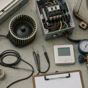
Fan wheel or blade condition, motor, bearings where serviceable, mounts, vibration, sound, rotation, speed taps or control, current, capacitor where applicable, airflow direction, and safeties are checked. A running motor does not prove useful airflow. Dirt, imbalance, loose mounts, incorrect rotation, control limits, or a slipping connection can reduce delivery and create recurring noise.
Check the coil and heat-transfer boundary
Coil cleanliness, fin condition, air bypass, entering and leaving air, water or refrigerant temperatures, valve response, piping, insulation, air in hydronic circuits, strainers where accessible, and central availability affect output. A clean fan coil cannot heat or cool without the correct source condition. Central plant or loop problems receive a routed owner rather than an unnecessary terminal-unit repair.
Verify filter and room air paths
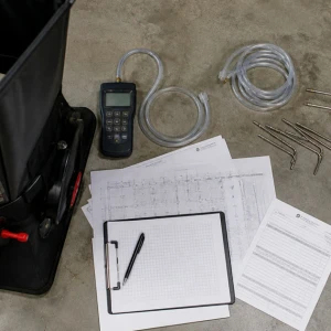
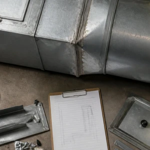
Filter type and fit, loading, bypass, return grille, cabinet leakage, supply outlet, furniture, partitions, doors, occupancy, and room geometry influence circulation. A blocked return or displaced grille can make a functional FCU appear undersized. Service compares local air temperatures and flow with actual room layout instead of judging performance only at the cabinet discharge.
Test valves, actuators, and local controls
Thermostat or sensor, setpoint, mode, fan command, valve command, actuator travel, linkage, valve stem, end switches, relays, controller outputs, interlocks, safeties, and feedback are compared with physical response. BAS-first programming remains outside, but the FCU service must determine whether an external command, local device, or mechanical condition is preventing operation.
Inspect condensate collection and removal
Drain pan, slope, corrosion, insulation, trap, line, pump where present, switch, cleanout, termination, and surrounding humidity are checked. Cooling coils can create water even when comfort seems acceptable. Overflow may damage ceilings and finishes. Drainage problems are corrected within scope or assigned to the responsible building system with clear access and restoration needs.
Separate FCU noise from building transmission
Fan imbalance, motor bearings, mounts, loose panels, duct or grille vibration, water velocity, valve noise, air in piping, structure, and room acoustics can produce different signatures. Sound is evaluated during relevant speeds and modes. Replacing a motor will not correct a vibrating panel or poorly isolated piping, so the report names the observed transmission path.
Coordinate ceiling and occupied-area work
Furniture, finishes, ceiling tiles, lifts, ladders, dust, water, electrical isolation, tenant schedules, privacy, security, and restoration shape execution. Drain and valve work may require wider protection than the unit footprint. The plan defines shutdown reach and confirms whether other terminals share water, refrigerant, controls, or electrical components before service begins.
Correct the confirmed terminal-unit fault
Repair may include cleaning, filters, fan or motor components, mounts, controls, sensors, actuators, valves, insulation, condensate parts, wiring, or accessible piping and refrigerant work within authorized scope. Evidence drives parts. Broad coil replacement, concealed piping, central hydronics, or building renovation receives an explicit project owner when the terminal unit is only one affected element.
Verify local and central relationships
Testing can include fan speeds, airflow, entering and leaving air, coil response, valve or refrigerant control, thermostat, alarms, condensate, shutdown, restart, and representative room conditions. Central plant availability and seasonal load may limit proof. The closeout distinguishes verified FCU correction from central conditions or occupied loads still requiring observation.
Receive an FCU-specific service record
ClimateService documents unit identity, served space, complaint, access, cabinet, filter, fan, motor, coil, valve or refrigerant interface, controls, condensate, air paths, central-system context, confirmed cause, completed work, readings, tests, restoration, limitations, open interfaces, and follow-up. Facility teams gain a repeatable baseline for similar units without assuming every FCU has the same condition.