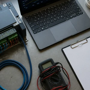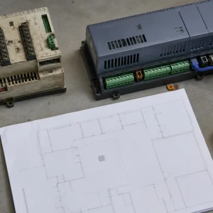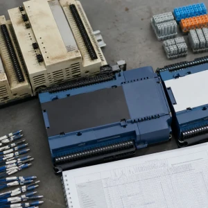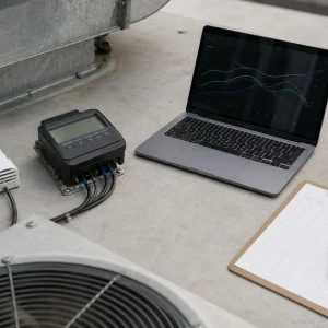


A commercial pneumatic-to-DDC retrofit replaces or integrates legacy air-powered thermostats, transmitters, controllers, relays, actuators, valves, and dampers with digital controls and usable building automation. ClimateService plans authorized Chicago conversions around occupied operations and the actual mechanical system. The page includes pneumatic thermostat replacement when it belongs to a broader conversion; isolated maintenance of an otherwise retained pneumatic system requires a narrower field scope.
Map the pneumatic system before conversion
Air compressors, dryers, filters, regulators, receivers, mains, branches, restrictors, thermostats, sensors, transmitters, receiver-controllers, relays, switches, actuators, valve bodies, dampers, gauges, panels, served zones, and connected equipment are inventoried. Tubing may be concealed or mislabeled, and several devices can share an air source. Field tracing prevents one visible thermostat from being mistaken for the entire control relationship.
Assess instrument-air condition and current reliability
Supply pressure, moisture, oil, leaks, compressor cycling, dryer performance, regulators, filters, tubing condition, fittings, calibration, response, and actuator operation show whether current complaints originate in the air system or individual controls. This evidence also informs phasing. A building may need reliable pneumatic operation during migration, so unstable instrument air cannot be ignored simply because digital conversion is planned.
Recover zone and equipment sequences
Thermostat behavior, reset schedules, receiver-controller logic, pressure relationships, day-night operation, summer-winter changeover, valve and damper action, fan and plant interlocks, freeze protection, safeties, and operator practice are documented. Old diagrams may not match current field operation. The future digital sequence should preserve approved intent while removing workarounds that no longer serve the building.
Decide which pneumatic devices remain temporarily
Some projects retain selected actuators or interfaces through transducers while controllers and sensors become digital; others replace the complete signal and actuation chain. Condition, leakage, stroke, torque, fail position, valve or damper mechanics, accessibility, compatibility, support, and future phases guide the decision. Interim mixed systems require clear ownership and should not become an undocumented permanent compromise.
Plan thermostat and sensor conversion by zone
Each pneumatic thermostat receives a verified zone, controlled equipment, tubing function, setpoint behavior, mounting condition, occupancy use, and replacement strategy. New digital sensors need appropriate variable, range, location, wiring or approved communication, wall condition, access, controller point, calibration, and labeling. Replacement should not copy a poor location that was affected by drafts, sunlight, wall cavities, or changed space use.
Create electrical and communication pathways
DDC controllers, sensors, actuators, relays, panels, transformers, power supplies, conduits, cable routes, networks, gateways, grounding, shielding, and access require coordination. Legacy pneumatic locations may have no suitable wiring path. The design addresses firestopping, finishes, occupied spaces, electrical boundaries, network ownership, spare capacity, and service access before devices are removed from the air system.
Sequence phases to keep the facility controllable
Phasing considers shared air supply, central equipment, terminal units, critical spaces, tenants, seasons, plant availability, temporary controls, old-to-new interfaces, shutdown reach, communication, rollback, and restoration. A floor, air handler, or equipment group may form a practical phase. Each transition needs a stable operating state and a way to identify which zones remain pneumatic.
Handle valves and dampers as mechanical assets
Digital actuators cannot correct a seized valve, damaged damper, loose linkage, leaking seat, wrong rotation, inadequate torque, poor authority, or inaccessible assembly. Stroke, closeoff, fail position, linkage, shaft, stem, blades, seals, airflow or water effect, and safe access are verified. Mechanical correction is coordinated rather than concealed with software offsets or excessive actuator force.
Program digital control with explicit fail states
Points, ranges, setpoints, schedules, resets, stages, modulation, minimum positions, alarms, histories, safeties, communication-loss behavior, power recovery, shutdown, and restart are defined from the approved sequence. The BAS should show command and useful feedback where available. Temporary overrides receive owners and expiration instead of becoming silent replacements for unfinished commissioning.
Commission every converted control chain
Point-to-point testing verifies digital sensors, controller inputs, outputs, relays, transducers, actuators, valve and damper motion, labels, scaling, and BAS representation. Functional testing follows schedule and demand through equipment and zone response. Representative heating, cooling, pressure, airflow, water, alarm, safety, loss-of-power, and restart states are tested when available; deferred seasons receive a follow-up plan.
Remove or identify abandoned pneumatic material
Disconnected tubing, devices, panels, compressor components, gauges, and abandoned interfaces should be removed or clearly identified according to project scope. Active retained pneumatic controls must remain labeled and documented. Ambiguous tubing left in walls or panels complicates future service. Final records distinguish active, temporarily retained, abandoned, and removed components by zone and equipment.
Transfer a complete conversion record
ClimateService documents the pneumatic inventory, retained and replaced devices, thermostat and zone map, sequences, electrical and network boundaries, programs and backups supplied, point list, calibration, valve and damper findings, phase status, functional tests, restored overrides, abandoned material, deferred conditions, limitations, and open work. Facility teams receive a clear digital baseline instead of a hidden mixture of air and electronic control.