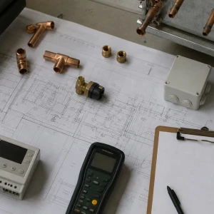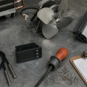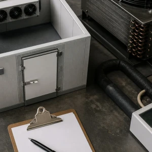


Commercial refrigeration repair protects product and operations by identifying why a fixed-site system cannot maintain its intended condition. ClimateService serves authorized Chicago facilities and follows the complaint across the refrigerated space, evaporator, condensing equipment, refrigerant circuit, controls, defrost, drainage, doors, insulation, loading, and surrounding environment. Transport refrigeration, trailers, trucks, and mobile units belong to a separate service boundary.
Protect product and record the failure state
Facility staff should follow their approved product-handling plan while the technician captures box or fixture temperatures, product history where supplied, alarms, setpoints, controller status, operating mode, door activity, loading, recent service, weather, and observed equipment state. Repeated resets can erase evidence. The service record separates measured conditions from unverified assumptions about product safety or regulatory disposition.
Define the stationary refrigeration system
The investigation maps the evaporator, condensing unit or rack connection where applicable, compressors, condenser, receiver, piping, metering device, valves, controls, drains, doors, panels, electrical supply, served space, and heat-rejection environment. Shared equipment can affect more than one fixture or room. Correct system identity prevents repair on a neighboring circuit that only appears similar.
Inspect airflow and evaporator condition
Fan operation, rotation, motors, blades, guards, coil cleanliness, ice pattern, air inlet and discharge, product clearance, drain pan, heaters, insulation, and temperature distribution are observed. A cold coil does not guarantee useful room airflow. Blocked return paths, stalled fans, heavy frost, damaged panels, or product placed against the evaporator can sustain warm zones after the refrigerant circuit starts.
Evaluate compressor and heat rejection
Compressor operation, starting components, oil observations where accessible, current, discharge condition, condenser fans, coil cleanliness, ambient recirculation, head-pressure control, receiver condition, vibration, and safeties are correlated. Rooftop, outdoor, and mechanical-room condensing equipment face different airflow and weather constraints. A protective shutdown is treated as evidence, not bypassed to force cooling.
Trace refrigerant-circuit evidence
Temperatures, pressures, line condition, piping support, insulation, sight indications where present, valve response, metering, evaporator feed, condenser response, and system history guide the diagnosis. Refrigerant handling follows qualified procedures. Adding charge without investigating leaks, system volume, airflow, heat rejection, controls, and previous work can hide the initiating problem and create a different operating fault.
Check defrost and low-temperature operation
Time, termination, fan delay, heaters or hot-gas components where applicable, sensors, controller settings, drain heat, ice pattern, recovery, and product-loading conditions are reviewed. Too little defrost can block airflow; unnecessary or incomplete defrost can raise temperatures and leave water or ice. The test follows the installed design rather than using one universal schedule for every application.
Review doors, panels, insulation, and infiltration
Gaskets, closers, hinges, sweeps, thresholds, door heaters where present, penetrations, panel joints, vapor barriers, damaged insulation, condensation, and traffic affect load. Refrigeration components may be functional while warm moist air enters faster than the system can remove it. Building-envelope findings are documented and assigned instead of being disguised as a compressor or refrigerant repair.
Verify controls, sensors, alarms, and power
Sensor placement and comparison, setpoints, differential, controller outputs, contactors, relays, fan and defrost commands, safeties, alarm history, wiring, disconnects, voltage, phase for applicable equipment, and BAS interfaces are checked within scope. A displayed temperature can be wrong because of sensor location, scaling, wiring, or air stratification. Controls are compared with physical operation.
Plan repair around facility operations
Product movement, access, roof work, occupied kitchens or stores, shutdown reach, shared circuits, electrical isolation, water and ice, parts, noise, sanitation boundaries, work hours, and temporary measures influence execution. The repair plan names what will stop, which spaces may be affected, what facility teams own, and how equipment and work areas will be restored.
Correct the proven failure boundary
Repair may involve electrical components, controls, sensors, fans, motors, drains, defrost components, valves, piping, refrigerant leaks, compressor or condenser work, door hardware, or a routed building-envelope correction. Exact work follows evidence and authorization. Broad installation or replacement planning receives a separate project scope when repeated failures, obsolete parts, inaccessible piping, or capacity limitations exceed a defensible repair.
Verify temperature recovery and stable operation
Testing may include compressor and fan operation, evaporator airflow, refrigerant response, controls, defrost, drainage, doors, alarms, cycling, representative space temperatures, and recovery under available load. Pull-down time depends on system and operating conditions and is not promised from one reading. Unavailable states receive monitoring points, expected conditions, owners, and response thresholds.
Receive a useful refrigeration repair record
ClimateService documents the complaint, system map, initial conditions, alarm and control evidence, confirmed cause, repaired items, refrigerant work where performed, settings, temperatures, electrical and mechanical tests, defrost and drainage observations, product or envelope boundaries, limitations, open work, and recommended follow-up. The closeout explains why the system failed and what now supports correction.