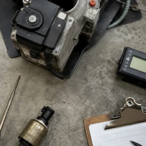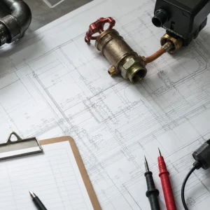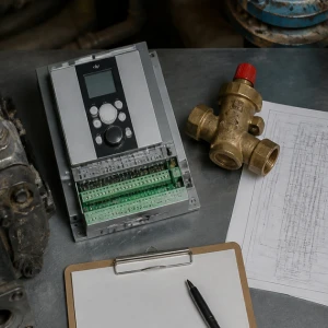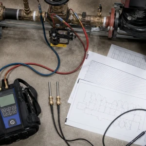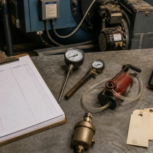


Commercial hydronic heating systems move heat through water, pumps, piping, valves, coils, and terminal equipment. ClimateService supports authorized Chicago facilities by tracing uneven heat, poor circulation, noise, pressure changes, leaks, air, and unstable temperature from the plant through the loop to representative spaces. Boiler repair, fan-coil equipment, airside TAB, and BAS programming remain separate when their components own the problem.
Define the hydronic system boundary
Heat source, pumps, primary and secondary loops, headers, branches, risers, expansion, air and dirt separation, strainers, valves, heat exchangers, coils, terminals, controls, and served areas are mapped. Building drawings may be incomplete. The field boundary identifies shared components and confirms whether the complaint affects one terminal, one branch, one loop, or the full plant.
Translate space symptoms into loop evidence
Cold zones, slow warm-up, overheating, noise, temperature swing, frequent air, valve complaints, and pump alarms are compared with schedules, outdoor conditions, supply and return temperatures, pressure, equipment calls, and representative terminals. A room symptom is not assumed to prove low flow. Envelope, airside, sensor, occupancy, and terminal faults are kept visible.
Evaluate pump operation and circulation
Pump status, rotation, speed, differential pressure, current, vibration, sound, seals, bearings where serviceable, check valves, isolation, strainers, bypasses, variable-speed commands, and proof are reviewed. A running motor does not establish correct water movement. Parallel pumps, minimum-flow paths, and common headers can produce misleading readings if the active configuration is not documented.
Check expansion, pressure, and air control
Static and operating pressure, expansion-tank connection and charge responsibility, makeup activity, relief discharge, high points, automatic vents, separators, drain points, pump location, and temperature change influence system stability. Repeated air can indicate pressure, leakage, makeup, or maintenance problems. The service records observations without making unsupported water-chemistry or vessel conclusions.
Inspect strainers, valves, and restrictions
Strainers, control valves, balancing valves, check valves, isolation valves, partially closed components, actuator travel, valve authority, debris, inaccessible handles, and unrecorded bypasses can change branch flow. Pressure and temperature evidence is gathered before disturbing positions. Valve changes are marked and restored or incorporated into an approved adjustment, preventing accidental loss of the existing baseline.
Correlate supply, return, and heat transfer
Plant supply temperature, branch temperatures, return temperature, delta-T, flow evidence, coil entering and leaving conditions, terminal air or surface response, valve position, and load are compared. A low delta-T can have several causes, including excessive flow, bypass, control behavior, or limited load. The report avoids treating one measurement as a universal diagnosis.
Review piping condition and insulation
Leaks, corrosion, supports, movement, noise, insulation damage, cold or hot surfaces, penetrations, flexible connectors, drains, vents, concealed routes, freeze exposure, and maintenance access are inspected where available. Active leaks and unsafe conditions receive containment and ownership. Broad piping replacement is separated from service work when reach, restoration, or engineering expands the project.
Test controls against physical response
Outdoor reset, loop setpoint, pump enable, differential-pressure control, valve commands, schedules, sensors, safeties, proof, alarms, and BAS trends are compared with pumps, valves, temperatures, and served conditions. Hydronic service proves interfaces far enough to establish cause. Network, graphics, supervisory programming, and controls modernization route to Controls/BAS.
Separate terminal problems from central problems
Fan coils, air handlers, unit heaters, radiators, radiant circuits, heat exchangers, and other terminals have local filters, fans, valves, traps, sensors, air paths, and access constraints. Representative checks determine whether the central loop can deliver required water conditions. Equipment-specific repair remains with the terminal owner when the branch supply is available and stable.
Correct the confirmed hydronic fault
Authorized work may include accessible pumps, seals, strainers, vents, gauges, sensors, actuators, valves, insulation, drains, minor piping, air removal, control settings, or approved circulation adjustments. Evidence drives the intervention. Major pumping changes, chemical cleaning, treatment, concealed piping, redesign, and full balancing receive a defined project or specialist owner.
Verify circulation across representative conditions
Testing can include pump starts and stops, speed response, pressure, temperatures, valve travel, alarms, air removal, leakage, representative branches, coil response, shutdown, and restart. Weather and load may prevent full-season proof. Readings are tied to the active lineup, tested zones, and control mode, with trend or return-test requirements listed.
Deliver a hydronic system record
ClimateService documents the mapped loop, equipment identity, active configuration, symptoms, pumps, pressure, expansion and air observations, strainers, valves, temperatures, terminals, controls, confirmed cause, completed work, changed positions, measurements, verification, limitations, and open owners. The handoff identifies inaccessible branches, seasonal load limits, restored valve positions, trend points, and the condition required for any return test. Facility teams gain a useful basis for repair, balancing, controls, maintenance, or capital decisions.