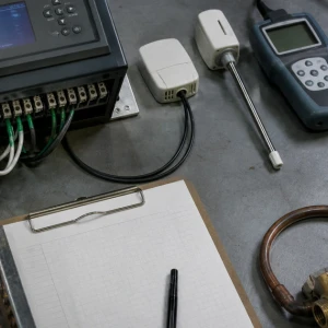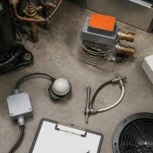


Data center cooling service addresses the facility context where IT heat load, airflow, environmental stability, and continuity must remain coordinated. ClimateService supports authorized Chicago data centers and comparable computing spaces by mapping precision equipment, supporting plant, containment, controls, alarms, power events, operating windows, and representative rack-inlet conditions. Precision cooling and CRAC/CRAH retain narrower system owners, while BAS and chiller work route outward when primary.
Define the protected computing environment
Room function, rack population, active and planned load, operating schedule, environmental criteria, containment, floor or overhead distribution, security, access, alarm thresholds, escalation contacts, and approved change process are documented. Facility criteria govern; service does not substitute universal setpoints or imply a certification. The boundary distinguishes a data hall from an adjacent office, electrical room, or generic server closet.
Map cooling equipment and shared dependencies
Precision units, comfort units serving critical areas, chilled-water plant, condenser systems, pumps, valves, refrigerant circuits, electrical feeds, controls, humidification, drainage, remote monitoring, standby equipment, and temporary cooling connections are mapped. Shared utilities can defeat apparent redundancy. The record identifies which dependency can remove multiple units at once and which owner controls it.
Relate active IT load to available operation
Rack density, active equipment, recent deployment changes, utilization pattern, running cooling units, fan speed, coil or circuit capacity, plant availability, maintenance state, and ambient conditions affect practical margin. Nameplate totals are not treated as usable capacity. Observed performance is separated from formal load calculation and engineering resilience analysis when those services are required.
Trace supply and return airflow
Cold-aisle delivery, rack inlets, hot-aisle return, containment doors and panels, blanking, floor tiles or overhead outlets, leakage, bypass, recirculation, cable openings, obstructions, filters, unit fans, and room pressure are reviewed. Airflow changes are coordinated so moving one tile or grille does not improve one rack while creating a neighboring hot spot.
Inspect precision units in facility context
Filters, fans, coils, compressors or chilled-water valves, pumps where present, refrigerant or water conditions, condensate, humidification, sensors, controls, alarms, cabinets, and service access are evaluated. The visit connects equipment behavior with data-hall conditions. A component repair is not declared successful until useful air and environmental response are observed at representative locations.
Coordinate controls, trends, and alarms
Unit setpoints, sensors, lead-lag, staging, fan control, alarm contacts, remote monitoring, BAS points, trend intervals, stale overrides, and notification paths influence response. Cooling service verifies field behavior and available evidence. Network communication, graphics, enterprise integrations, and supervisory programming remain with Controls/BAS once the fault becomes controls-first.
Plan intervention around live operations
Maintenance window, load state, redundant path, temporary monitoring, isolation, rollback point, tool and material control, dust, water, security escort, communications, approval, and restart sequence shape work. A filter, fan, valve, or drain intervention can change pressure and temperature quickly. The protected state and stop conditions are agreed before a unit is opened or disabled.
Respond to alarms without erasing evidence
Alarm code, timestamp, affected unit, room conditions, recent changes, power events, plant status, controls trends, prior resets, and operator actions are captured. Cycling equipment may clear the display but hide the cause. Immediate stabilization, containment, load coordination, temporary measures, and escalation are separated from permanent repair and documented with authorization limits.
Evaluate redundancy as an operating condition
Installed spare units do not automatically prove usable redundancy. Shared power, controls, piping, valves, drains, airflow paths, sensor errors, unavailable equipment, simultaneous maintenance, and current load can remove margin. Service records observed readiness and authorized transition tests without certifying N+1 or another resilience level beyond the approved basis.
Verify recovery at representative rack inlets
Testing can include unit enable, fans, coils or circuits, supply and return conditions, temperature, humidity where relevant, condensate, controls, alarms, restart, failover where authorized, trend stabilization, and selected rack inlets. The test load, duration, access, and ambient conditions are recorded. Short recovery at one sensor is not generalized across the room.
Route plant and project findings correctly
Chiller or cooling-tower failures, BAS networks, electrical capacity, containment construction, rack deployment, replacement planning, and capital projects may own the next action. Data center cooling service documents the interface and evidence but does not duplicate those owners. This preserves a clear route from facility symptom to system-specific correction and accountable closure.
Deliver an operations-ready cooling record
ClimateService documents protected spaces, active load context, equipment map, running and standby state, airflow observations, inlet readings, controls, alarms, dependencies, authorized work, change window, tests, recovery, trends, limitations, rollback actions, open owners, and escalation contacts. Operations and facility teams receive a shared factual baseline for the next maintenance window or alarm.