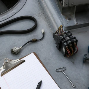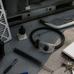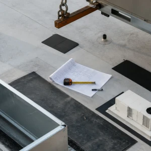


RTU controls and economizer service connects controller commands to real damper movement, mixed-air conditions, refrigeration stages, heating, relief, ventilation, and occupied-zone response. A BAS point can look normal while linkage is disconnected or a sensor represents the wrong air stream. ClimateService evaluates authorized Chicago unit-level systems while building-wide automation, ventilation design, life-safety, and network ownership remain separate.
Define the operating complaint precisely
Identify RTU and zones, schedule, occupancy, setpoints, weather, outdoor conditions, complaint timing, ventilation concern, energy observation, alarms, overrides, recent control work, and affected cooling or heating mode. Economizer troubleshooting should begin with a behavior such as unwanted outdoor air, no free cooling, unstable discharge air, or failed ventilation response.
Establish the intended sequence
Document unit enable, occupied and unoccupied operation, fan proof, minimum damper position, outdoor-air enable, high and low limits, differential logic, mechanical cooling integration, heating lockout, relief, safeties, alarms, minimum times, and restart. Conflicts between design, submittal, program, and operator expectation require responsible resolution before changes.
Inspect the outdoor-air and return paths
Hood, screens, filters, blades, seals, shafts, bearings, linkage, actuator, minimum-position hardware, return damper, relief or exhaust, partitions, mixed-air chamber, coil protection, and physical obstructions can defeat correct commands. Water, snow, ice, corrosion, debris, or cabinet distortion may create seasonal faults.
Verify sensors against representative air
Outdoor, return, mixed and discharge temperature, humidity, carbon dioxide where part of approved design, enthalpy, pressure, and other sensors should be checked for location, mounting, wiring, range, bias, aspiration, and reference comparison. A sensor affected by sun, coil radiation, leakage, or stratification can mislead sound logic.
Trace command through actuator and feedback
Controller output, relay, power, wiring, actuator, rotation, linkage, end stops, blade position, torque, feedback, and physical airflow form the command chain. Calibration or stroke should follow equipment procedures. Software position should not be treated as proof when the connected blades do not move through the required range.
Correlate mixed air with airflow and load
Fan operation, filter loading, return path, supply airflow, duct pressure, building pressure, exhaust, wind, door position, occupancy, and load influence measured mixed air. Economizer operation cannot be interpreted from sensor values alone if the fan, dampers, or distribution do not establish expected airflow paths.
Coordinate mechanical cooling and heating stages
Compressor enable, stages, low-ambient controls, coil freeze protection, discharge-air limits, heating stages, heat-pump changeover, safeties, and anti-cycle timing interact with outdoor air. Poor transitions can create simultaneous heating and cooling, coil icing, comfort swings, or repeated trips even when each component operates independently.
Review minimum outdoor air and relief boundaries
Approved ventilation and pressure requirements come from responsible design and facility programs. Service can verify damper movement, settings supplied by the project, sensors, airflow evidence, relief response, and schedules. It should not invent an outdoor-air percentage or claim compliance from actuator position without appropriate measurement and authority.
Check BAS points without absorbing building-wide ownership
Commands, setpoints, schedules, status, alarms, trends, priorities, overrides, communication, and time may be compared between supervisory and local controls. Network, server, cybersecurity, global programming, life-safety, and multi-unit optimization remain separate authorized scopes. Local correction should not create hidden effects elsewhere.
Control temporary overrides and changes
An override should record reason, points, person, approval, risk, monitoring, expiration, and restoration. Permanent changes need backups, expected result, functional test, and rollback. Forgotten forced dampers or temperatures can waste energy, expose coils, or hide failed hardware for months.
Functionally test through available conditions
Testing may observe or simulate enable, fan proof, sensor response, minimum position, full stroke, free-cooling transition, mechanical cooling, heating lockout, relief, limits, safeties, alarms, shutdown, restart, and zone response. Simulations should remain controlled and not defeat safety functions. Weather-limited tests need planned follow-up.
Use focused trends for intermittent faults
Purposeful trends can compare enable, outdoor, return, mixed and discharge conditions, damper command and feedback, fan proof, compressor stages, heat, alarms, and zone response during the problem window. Sampling interval and duration should match the behavior. Endless point collection creates noise, while one screenshot without weather, load, and physical position rarely proves economizer performance.
Protect the corrected baseline
Final sensor offsets, minimum and maximum positions, limits, schedules, priorities, controller settings, sequence version where relevant, backups, and restored overrides should be recorded. Later changes need reason, authorization, test result, date, and rollback path. This prevents an emergency forced position from becoming permanent hidden logic that defeats ventilation, free cooling, or coil protection.
ClimateService transfers a defensible unit-level baseline
ClimateService documents complaint, intended sequence, physical assembly, sensor checks, commands, damper response, settings, controls changes, restored overrides, functional results, unavailable weather, open airflow or BAS work, and monitoring within its scope. Facility teams receive evidence that separates hardware, unit logic, distribution, design, and supervisory ownership.