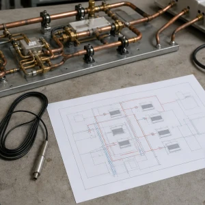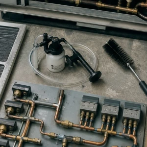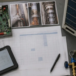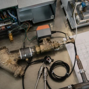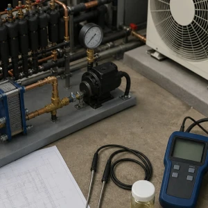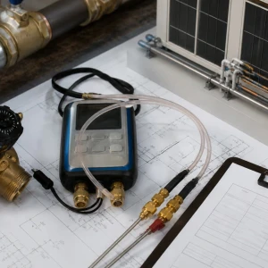


Commercial VRF and VRV installation is a system project that connects building loads and zones to outdoor modules, indoor units, refrigerant piping, branch devices, condensate, power, communication, controllers, ventilation strategy, and service access. ClimateService coordinates authorized Chicago installation while design, structural, electrical, life-safety, controls, ventilation, code, and owner responsibilities remain assigned.
Define why VRF fits the building
Clarify project goals, existing constraints, zoning needs, simultaneous heating and cooling, schedules, occupancy, envelope, internal loads, ventilation, humidity, acoustics, space limitations, future changes, criticality, and owner operations. VRF should be selected through qualified project analysis rather than as a default substitute for every conventional system.
Establish room-by-room loads and zones
Perimeter orientation, people, lighting, equipment, envelope, schedules, diversity, outdoor air, infiltration, ceiling conditions, and future tenancy affect zone duty. Indoor-unit type and capacity should follow approved calculations. Oversized small zones and poorly grouped spaces can create unstable cycling or incompatible mode expectations.
Select the correct system architecture
Heat-pump or heat-recovery configuration, air-source, water-source, or geothermal heat rejection, module combinations, connected capacity, diversity, piping limits, branch selectors, indoor-unit types, low-temperature needs, redundancy, controls, sound, and service access shape design. Manufacturer selection data should match the approved operating basis.
Coordinate outdoor-module placement
Roof, grade, screen, platform, structural support, operating weight, vibration, snow, wind, heat, coil airflow, recirculation, sound, drainage, access, lifting, neighboring property, exhausts, and future service clearances affect placement. Qualified structural and rigging parties approve their boundaries.
Lay out refrigerant piping deliberately
Pipe sizes, total and equivalent lengths, vertical separation, branches, selector boxes, oil return, support spacing, expansion, insulation, vapor sealing, shafts, sleeves, firestopping, joints, isolation where approved, labels, and service access influence reliability. Field routing should not casually depart from engineered and manufacturer limits.
Control joint quality and cleanliness
Storage, cutting, deburring, nitrogen purge during brazing where required, approved flaring or connection methods, torque, contamination control, pressure testing, leak testing, evacuation, dehydration, and documentation protect the refrigerant network. Open piping should remain capped. A large shared charge makes concealed workmanship especially important.
Install indoor units for air and service
Cassettes, ducted units, wall units, floor units, and air handlers require suitable support, level, return and supply paths, filters, clearances, ceiling access, vibration control, acoustics, sensors, louvers, and distribution. Decorative fit should not eliminate access to boards, fans, valves, pans, pumps, and piping connections.
Design condensate as a complete path
Pans, pumps, floats, traps, slope, pipe size, vents where applicable, insulation, cleanouts, supports, termination, leak protection, ceiling risk, and testing deserve their own coordination. A cooling system can operate correctly and still damage the building through an inaccessible or untested drain path.
Coordinate electrical and communication networks
Voltage, phase, capacity, disconnects, overcurrent protection, grounding, control power, indoor and outdoor feeds, communication cable type, polarity, shielding, topology, separation, termination, addresses, gateways, and panels require approved trade coordination. Wiring documentation should reflect installed, not assumed, device relationships.
Integrate controllers and building operation
Local and central controllers, schedules, setpoints, mode arbitration, heat-recovery requests, occupancy, locks, alarms, BAS gateways, ventilation interlocks, life-safety interfaces, restart, and trend needs should follow an approved sequence. Building-wide BAS architecture remains separate, but integration points require end-to-end tests.
Commission beyond individual equipment startup
Checks may include system map, pressure and evacuation records, charge, addresses, communication, indoor fans, drains, valves, branch devices, outdoor modules, compressor and fan staging, heating, cooling, heat recovery, defrost, controllers, alarms, simultaneous zones, and representative spaces. Seasonal limits need deferred tests.
Coordinate ventilation as a parallel system
Many VRF projects use separate outdoor-air equipment, energy recovery, exhaust, or building pressure control. Supply locations, schedules, conditioning, humidity, filtration, balancing, controls, freeze protection, alarms, and zone distribution should be coordinated with VRF operation. The VRF indoor unit should not be assumed to deliver required ventilation simply because it circulates room air.
Protect the project through construction
Ceiling dust, open piping, moisture, unsealed ducts, temporary power, incomplete drains, damaged insulation, moved sensors, blocked return paths, and unauthorized controller use can compromise an otherwise sound installation. The project should define caps, covers, temporary filters, pressure retention, inspections before concealment, cleanliness, access-panel coordination, and authorization before energizing equipment.
Prepare facility staff for multi-zone ownership
Operators should receive the asset and zone map, controller hierarchy, normal schedules, mode arbitration, alarm route, filter and drain locations, roof access, shutdown contacts, and rules for overrides. Training should use actual installed controllers and representative units. Without that handoff, occupants may create conflicting modes or facilities may miss hidden maintenance points.
Close deferred seasonal conditions
Weather or occupancy may prevent full heating, cooling, heat-recovery, defrost, low-temperature, humidity, or maximum-connected-load proof. The commissioning record should name each deferred condition, required zones and modes, measurements, responsible company, target window, and corrective path. This turns an honest limitation into a controlled acceptance item rather than a forgotten gap.
ClimateService transfers a maintainable network
ClimateService documents installed equipment, zone and device relationships, piping and branch records, test results, settings, photographs, commissioned modes, unavailable conditions, open interfaces, filters, drain access, warranties, maintenance requirements, and seasonal follow-up within its scope. Facility teams receive a usable system baseline instead of isolated equipment manuals.