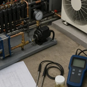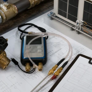


Commercial VRF and VRV repair requires system-level diagnosis because many indoor units share outdoor modules, refrigerant piping, branch or heat-recovery devices, communication, power, controls, and operating limits. One uncomfortable zone can reflect a local fan or drain problem, a network issue, or a condition affecting the entire refrigerant system. ClimateService investigates authorized Chicago systems from the failure pattern and verifies correction without treating an error code as the cause.
Map the affected zones and system architecture
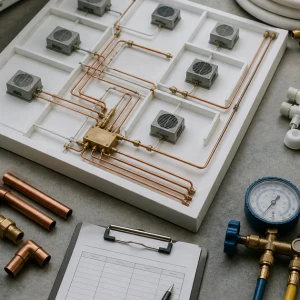
Identify outdoor modules, indoor units, branch controllers or selector boxes, refrigerant circuits, controllers, served spaces, schedules, occupancy, simultaneous modes, complaint timing, weather, alarms, and recent work. Accurate addresses and relationships matter. A unit name on a wall controller may not reveal which shared equipment or branch serves it.
Capture the fault before clearing history
Commands, modes, setpoints, indoor fan, temperatures, outdoor operation, error history, communication status, protection events, drainage, and available trends should be preserved while the issue exists when safe. Repeated resets can erase sequence and force the technician to wait for the same operating condition to return.
Separate local indoor-unit faults
Filters, coil, fan wheel, motor, louvers, sensors, electronic expansion device, drain pan, pump, trap, insulation, condensate line, controller, power, wiring, and access can create a single-zone complaint. Ceiling and occupied-space protection matters. Water staining may originate from icing, blocked drainage, poor insulation, or another building source.
Evaluate outdoor-module operation
Compressors, inverter drives, fans, coils, sensors, valves, oil management, piping, safeties, current, weather exposure, airflow clearance, snow or debris, and module staging influence shared capacity. Manufacturer procedures and qualified electrical and refrigerant practices apply. A module alarm may be responding to a field or indoor-unit condition.
Trace refrigerant distribution and branch devices
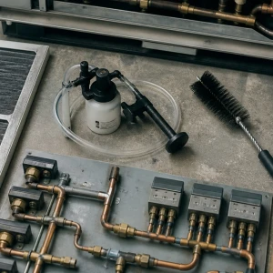
Pipe sizes, routing, support, insulation, joints, branch fittings, selector boxes, valves, electronic devices, temperature patterns, oil return, vertical separation, system charge, and previous modifications affect delivery. Leak investigation and charging should follow approved procedures. Adding refrigerant without proving leak, volume, evacuation, and distribution conditions can worsen performance.
Check heat-recovery and simultaneous-mode logic
Heat-recovery systems coordinate zones requesting heating and cooling through branch devices and control logic. Conflicting modes, selector response, sensor bias, communication, capacity limits, defrost, and system priority can create intermittent complaints. Testing should include the actual mix of zone demands rather than one indoor unit in isolation.
Verify communication and addressing
Network wiring, polarity, shielding, grounding, topology, addresses, duplicate devices, connectors, controller power, gateways, termination, noise, and recent replacements may affect several units. Diagnostic information should be compared with physical devices. Network changes and vendor-specific procedures need authorization and documented backups where available.
Correlate controls with physical response
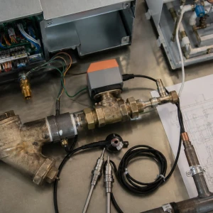
Local controllers, central controllers, schedules, setpoints, locks, mode arbitration, occupancy, BAS gateways, overrides, alarms, and restart behavior should be matched to fan, valve, compressor, and zone response. BAS-first programming ownership remains separate, but VRF repair should identify when external commands prevent valid mechanical operation.
Inspect power and protective conditions
Disconnects, breakers, fuses, terminals, communication power, voltage, phase for applicable equipment, grounding, boards, drives, motors, heaters, and safeties can interrupt a device or network. Protection should not be bypassed to force operation. Qualified work should identify whether the initiating condition is electrical, mechanical, refrigerant, or control-related.
Plan repair across occupied zones
Ceiling access, tenant notice, furniture and finish protection, lifts, roof or yard access, refrigerant isolation, shutdown reach, shared-system consequence, parts, controls access, noise, work hours, and temporary conditioning influence execution. A repair to one branch may affect many spaces. The plan should name boundaries and restoration steps.
Verify local and shared system results
Testing may include indoor fan, air temperatures, drainage, valves, outdoor modules, compressor and fan staging, refrigerant response, branch operation, simultaneous modes, communication, controllers, alarms, and representative zones. Weather or load may limit proof. Deferred conditions need readings, owners, and response thresholds.
Monitor the conditions that produced the failure
A simultaneous-mode conflict, high outdoor load, low-temperature defrost event, drain-pump alarm, communication interruption, or capacity allocation problem may not repeat during a short visit. The closeout should identify necessary zones, modes, weather, schedule, readings, error history, responsible reviewer, and response threshold. Focused follow-up converts intermittent behavior into evidence instead of encouraging repeated resets.
Decide when repair has become a larger system project
Recurring refrigerant leaks, obsolete boards, repeated compressor damage, branch-device failure, inaccessible piping, communication instability, capacity shortfall, or widespread indoor-unit deterioration may justify replacement or upgrade planning. The decision should compare verified cause, shared reach, repair history, parts, downtime, access, building plans, and supported options rather than use one alarm or system age alone.
ClimateService leaves a multi-zone repair baseline
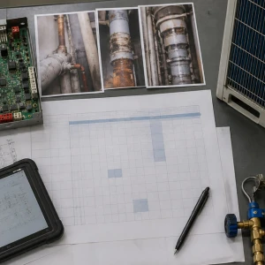
ClimateService documents system map, complaint, error and operating evidence, confirmed cause, repaired devices, refrigerant work, controls context, settings, photographs, tested zones and modes, unavailable conditions, open building interfaces, and next maintenance within its scope. Facility teams receive continuity without unsupported claims that one cleared code guarantees every zone or future operating state.