

Commercial geothermal VRF service joins multi-zone refrigerant equipment to a ground-source water loop whose temperature and flow change with building demand, season, soil, borefield or horizontal-loop performance, pumps, heat exchangers, fluid, controls, and maintenance history. ClimateService evaluates authorized Chicago mechanical interfaces while loop-field design, drilling, geology, treatment, and engineering remain with qualified parties.
Map the complete geothermal VRF system
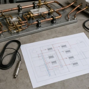
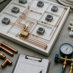
Identify water-source VRF modules, indoor units, branch devices, refrigerant circuits, pumps, headers, loop zones, heat exchangers, expansion, air separation, makeup, valves, strainers, fluid, controls, meters, served spaces, schedules, and available design records. The map distinguishes cabinet, building-loop, and ground-loop ownership.
Define the complaint with seasonal context
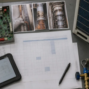
Record affected zones and modes, time, weather, load, loop entering and leaving temperatures, pump and valve state, pressure or flow evidence, alarms, recent drain-down or fluid work, and whether other modules are affected. Long seasonal temperature drift and short-term equipment faults require different evidence.
Inspect module and branch water components
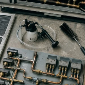
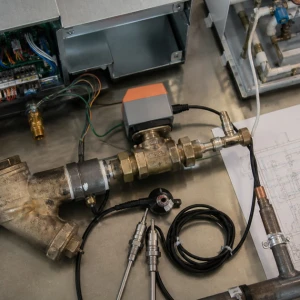
Isolation and control valves, actuators, strainers, hoses, pipes, insulation, vents, drains, heat exchangers, leaks, corrosion, supports, temperature sensors, flow proof, and access influence each VRF module. Actual water movement should be verified; command, actuator position, or pump status alone does not prove branch flow.
Correlate temperatures, flow, and load
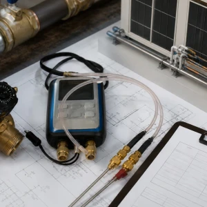
Entering and leaving fluid temperature, differential, pressure or flow where authorized, valve authority, pump speed, concurrent module demand, refrigerant stages, and sensor accuracy should be compared. Measurements outside the failure window can miss peak heating extraction, cooling rejection, low-load instability, or an imbalanced branch.
Evaluate refrigerant response to loop conditions
Compressors, inverter drives, valves, refrigerant temperatures and pressures, piping, oil evidence, safeties, current, and staging depend on usable water-side heat exchange. Low flow, fouling, air, sensor bias, or extreme entering fluid temperature can cause protection that resembles refrigerant or board failure.
Review pumps, pressure, and loop distribution
Pump staging, variable drives, differential-pressure control, balancing valves, bypasses, strainers, air separators, expansion tank, makeup, branch pressure, isolation, and simultaneous demand affect circulation. VRF service can identify system effects, while generic hydronic redesign and formal balancing remain separate qualified scopes.
Inspect fluid and heat-exchanger context
Antifreeze type and concentration where used, water quality, debris, corrosion, scale, biological material, filters, strainers, plate heat exchangers, cleaning, flushing, sampling, and recent additions can influence performance. Qualified fluid or treatment providers interpret chemistry and freeze protection; mechanical observations do not replace their program.
Respect the ground-loop boundary
Borefields or horizontal loops, headers, vaults, buried joints, purge ports, pressure, temperature history, field balance, leaks, soil and groundwater assumptions, and thermal capacity may require specialist investigation. ClimateService can document loop-side evidence and coordinate access but should not infer subsurface condition from one cabinet reading.
Trace controls through the shared system
Module demand, water valves, flow proof, pump command, differential pressure, loop temperatures, safeties, alarms, schedules, BAS points, overrides, seasonal modes, and restart should be followed from command to physical response. External supervisory changes require authorized controls ownership and records.
Plan service without destabilizing the loop
Isolation, drain-down, fluid capture, air removal, refill, purge, affected modules and zones, weather, load, pump availability, access, temporary conditioning, treatment or antifreeze restoration, and communication shape work. An open branch can introduce air or fluid imbalance beyond the visible module.
Verify cabinet, loop, and zones together
Testing may include branch flow evidence, fluid temperatures, valves, strainers, pumps, pressure control, refrigerant response, indoor units, branch devices, controls, alarms, and representative zones. Seasonal or ground-loop-load limitations should receive deferred observations and responsible owners rather than unsupported conclusions.
Use long-term trends to distinguish field and building effects
Seasonal entering fluid temperature, building load, pump speed, differential pressure, module demand, heat-rejection or extraction balance, alarms, weather, and energy observations can show whether the ground loop is drifting or one branch is underperforming. Trend interpretation may require qualified engineering. Mechanical records should preserve context instead of claiming subsurface failure from a short visit.
Protect freeze performance and fluid records
Fluid type, concentration, test method, date, sample point, temperature basis, additions, dilution, disposal, and provider recommendations should remain traceable. An incorrect mixture can change freeze protection, pumping, heat transfer, and material compatibility. ClimateService coordinates authorized mechanical work; qualified fluid and design parties approve targets and corrective treatment.
Plan recovery from air and low-flow events
After opening a branch, pump replacement, leak repair, or fluid addition, the system may require controlled fill, purge, air separation, expansion review, pump checks, valve restoration, and observation across modules. Local flow can appear stable while trapped air migrates. The handoff should name follow-up points, responsible staff, and alarm or pressure thresholds.
Route capacity questions into evidence-based review
If loop temperatures repeatedly approach limits during peak heating or cooling, compare actual building load, operating modules, pump delivery, controls, fluid, heat exchangers, field history, and design assumptions. Repairing one VRF cabinet will not correct an undersized or degraded ground field. Conversely, one failed sensor should not trigger a major geothermal project.
ClimateService delivers a geothermal VRF baseline
ClimateService documents system map, complaint context, water and refrigerant evidence, corrected module components, pump and loop coordination, settings, photographs, tested modes, unavailable conditions, open ground-loop or fluid work, and next maintenance within its scope. Facility teams receive clear boundaries and comparable seasonal records instead of cabinet-only service.