

Boiler and cooling-tower integration for water-source VRF controls how a shared loop absorbs, rejects, stores, and redistributes heat as zones change between heating and cooling. Modules, pumps, towers, boilers, heat exchangers, valves, sensors, treatment, and BAS logic must follow a coherent sequence. ClimateService supports authorized Chicago VRF integration while generic plant design and equipment ownership remain explicit.
Map the entire heat-sharing system
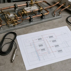
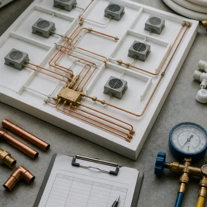
Identify VRF modules and branches, indoor-zone demand, loop mains, pumps, bypasses, heat exchangers, towers, boilers, expansion, air separation, makeup, treatment, valves, sensors, meters, controllers, safeties, alarms, and available sequence documents. The map should show which devices are enabled by temperature, demand, schedule, or protection.
Define the operating complaint and consequence
Record affected zones, modes, time, weather, loop temperatures, pump state, active modules, tower fans and pumps, boiler stages, valves, alarms, overrides, recent work, and whether the problem occurs during peak load, low load, morning warm-up, or seasonal transition. Different windows reveal different sequence gaps.
Establish approved loop-temperature strategy
Normal range, heating and cooling limits, deadbands, enable and disable thresholds, reset logic, minimum runtime, freeze protection, heat-exchanger boundaries, module requirements, and owner goals should come from approved design and manufacturer information. Service should verify execution, not invent setpoints from one comfortable day.
Verify pumps and water distribution first
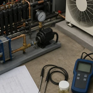
Pump staging, speed commands, differential-pressure sensors, bypasses, check valves, balancing valves, strainers, air, expansion, flow proof, and shared demand determine whether heat reaches plant equipment and VRF modules. Tower or boiler staging cannot correct a closed valve, failed pump, plugged strainer, or unstable pressure loop.
Test cooling-tower enable and response
Tower availability, isolation, basin and pumps, fans, drives, cells, water temperatures, freeze strategy, minimum flow, bypass, controls, alarms, treatment, and seasonal readiness influence heat rejection. VRF integration service correlates plant response with module demand; complete tower maintenance or repair remains its own service owner.
Test boiler and heat-addition response
Boiler availability, isolation, pumps, heat exchanger, valves, firing or stage command, safeties, return temperature, minimum flow, venting, fuel, alarms, and seasonal readiness influence loop heating. Qualified boiler parties own combustion and boiler internals. Integration testing verifies the approved interface and effect on VRF operation.
Coordinate simultaneous heating and cooling
VRF zones may transfer heat internally while the shared loop remains within range without tower or boiler operation. Controls should recognize net load, module diversity, temperature trend, minimum equipment operation, and transition timing. Unnecessary plant staging wastes energy; delayed staging can drive modules toward capacity or protection limits.
Trace sensors, commands, and physical action
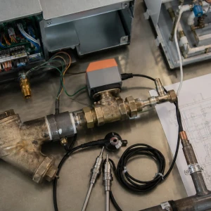
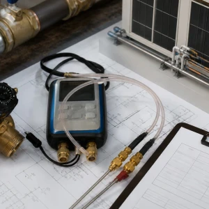
Loop sensors, locations, calibration, controller inputs, outputs, relays, drives, valve actuators, equipment enables, proofs, alarms, BAS points, priorities, schedules, and overrides form a chain. A command or status point does not prove flow, heat transfer, fan operation, or firing. Physical response and temperatures complete the test.
Manage seasonal transitions and low-load behavior
Spring and fall can produce rapid changes, mixed zone demand, tower freeze concerns, boiler minimums, pump turndown, temperature overshoot, and cycling. The sequence should handle lockouts, deadbands, minimum times, reset, and recovery without manual seasonal overrides that remain forgotten after weather changes.
Coordinate water treatment and shutdowns
Makeup, blowdown, chemical feed, fluid, filtration, strainers, cleaning, drain-down, refill, sampling, and treatment restoration influence towers, heat exchangers, boilers, piping, and modules. Treatment providers and responsible plant parties own their program. Integration projects should define isolation and restoration so controls testing does not disrupt water quality.
Functionally test transitions and failure response
Testing may observe cooling-only, heating-only, mixed demand, tower enable and disable, boiler enable and disable, pump staging, temperature recovery, safeties, alarms, loss of proof, overrides, shutdown, restart, and representative zones. Weather limits may require controlled simulation or deferred seasonal testing under approved procedures.
Use focused trends across changeover windows
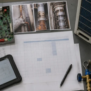
Purposeful trends can compare net VRF demand, loop temperatures, pump speed, differential pressure, tower and boiler commands, physical proofs, valve positions, alarms, weather, and representative zones before, during, and after a transition. Sampling should match the event. An isolated screenshot cannot show overshoot, delayed staging, unstable deadband, or a forgotten override.
Protect manual-operation and failure plans
Facilities need authorized steps for sensor failure, lost proof, unavailable tower or boiler, pump fault, extreme weather, and BAS interruption. Temporary manual operation should define equipment limits, freeze or over-temperature risk, monitoring, person responsible, expiration, and restoration. It should never rely on defeating safeties or leaving plant equipment forced indefinitely.
Preserve owner training and sequence records
Operators should understand normal loop range, expected tower and boiler enable, pump behavior, seasonal locks, alarms, override policy, treatment contacts, and how VRF zone demand affects the plant. Final sequence, point list, setpoints, backups, test results, and open items should be stored where future service teams can find them.
ClimateService transfers a traceable integration baseline
ClimateService documents system map, approved sequence supplied, sensor and device checks, operating states, commands and physical responses, temperatures, settings, restored overrides, tests, unavailable conditions, open tower, boiler, hydronic, treatment, or BAS work, and monitoring within its scope. Facility teams receive a baseline that preserves clear equipment ownership.