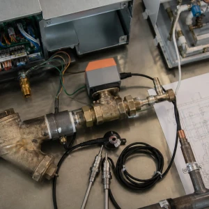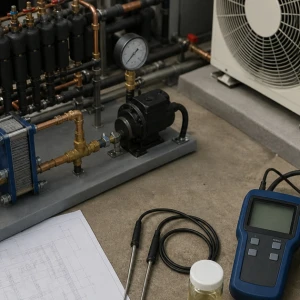


Condenser-water loop balancing for VRF is a system-specific service that aligns documented module requirements with actual branch flow, pressure, valve authority, pumps, shared demand, heat rejection or addition, and controls. It is not random throttling to make one cabinet quieter. ClimateService supports authorized Chicago VRF water-loop scope while design flow, hydronic redesign, treatment, tower, boiler, and engineering ownership remain explicit.
Define the problem balancing should solve
Record affected modules and zones, capacity or trip symptoms, time, weather, load, loop temperatures, pump state, valve position, alarms, recent changes, and whether the issue shifts as other equipment starts. Balancing is appropriate when distribution evidence exists. A failed actuator, dirty strainer, sensor bias, or inadequate plant temperature needs different correction.
Build an accurate circuit map
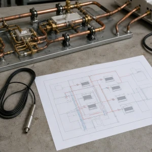
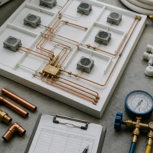
Identify pumps, headers, mains, branches, module connections, valves, strainers, bypasses, heat exchangers, towers, boilers, expansion, air separation, controls, meters, pipe sizes, design data, and simultaneous consumers. Field tags and drawings should be reconciled. Unknown valve identity makes repeatable adjustment and restoration impossible.
Establish approved flow requirements
Manufacturer data, project schedules, module capacity, operating modes, fluid properties, temperature basis, diversity, minimum and maximum flow, heat exchangers, and design documents inform targets. Nameplate connection size does not define flow. When design data conflicts or is missing, responsible engineering should resolve the basis before final balancing.
Verify prerequisites before measurement
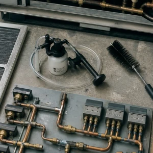
Strainers, isolation valves, control valves, actuators, pumps, drives, air removal, expansion, fluid level, leaks, sensors, heat exchangers, treatment, and loop cleanliness should be in serviceable condition. Balancing around a plugged strainer or trapped air creates false settings that change as soon as maintenance is completed.
Select repeatable measurement methods
Calibrated balancing valves, differential pressure, approved flow meters, ultrasonic methods where suitable, temperature, pump data, and equipment-provided flow proof may contribute. Instrument accuracy, straight runs, fluid properties, valve curves, sensor location, range, and operating stability affect results. Assumptions should be separated from measured values.
Capture the operating condition with every reading
Active modules, indoor demand, pump speed, valve commands, bypass position, loop temperatures, tower or boiler state, weather, and other consumers should accompany flow or pressure readings. A balanced condition at low load may not represent peak operation. Repeatable records allow later comparison instead of relying on valve turns.
Evaluate pump and pressure control
Pump staging, variable-speed commands, differential-pressure sensor location, setpoint, minimum speed, bypasses, parallel pumps, check valves, strainers, and system curve influence branch delivery. Excess pressure can create noise and poor valve authority; insufficient pressure starves remote modules. Pump-control changes require approved ownership and functional testing.
Adjust branches in a controlled sequence
Balancing should follow an approved proportional or project method, with valves identified, starting positions recorded, critical circuits recognized, control valves driven to the intended condition, and adjustments repeated as interactions settle. Locking or marking final positions supports restoration. A single pass from the mechanical-room entrance outward is not reliable evidence.
Correlate flow with module and zone response
Entering and leaving water, module demand, compressor stages, refrigerant response, safeties, current, alarms, indoor units, and representative zone temperatures help confirm that flow supports actual operation. Correct branch flow cannot repair a refrigerant, airflow, controller, or load problem, and zone improvement alone does not prove every circuit.
Coordinate tower, boiler, and treatment boundaries
Plant temperatures, tower or boiler availability, heat exchanger condition, treatment, filters, blowdown, makeup, fluid, and seasonal sequence influence results. VRF balancing should document these dependencies and route separate plant work. It must not redefine tower, boiler, water-treatment, or building-loop design without authorized scope.
Verify at representative load and transitions
Final checks should include documented active equipment, pump and control state, target and measured values, valve positions, loop temperatures, module response, alarms, and remote or critical branches. Seasonal limits may require follow-up under higher heating or cooling demand. Deferred conditions need owners and thresholds.
Protect settings after service and repairs
Valve replacement, strainer cleaning, pump work, controller changes, tenant buildouts, module additions, heat-exchanger cleaning, and seasonal overrides can alter the balanced condition. The facility should define who may adjust final positions or pressure setpoints, how changes are recorded, and when remeasurement is required. Locking devices and marks support control but do not replace a current circuit schedule.
Plan seasonal confirmation for both net loads
A loop balanced during cooling-dominant operation may behave differently during heating-dominant demand, tower-to-boiler transition, or low-load periods. The closeout should identify critical branches, target weather or demand, active equipment, readings, pump state, and responsible reviewer for the opposite season. This confirms distribution without pretending one operating snapshot represents the entire year.
Route design limitations without hiding them
If required branch flow cannot be achieved with clean components and suitable pump operation, document available pressure, valve authority, pipe constraints, simultaneous demand, module needs, and observed effect. Qualified hydronic or project design may be necessary. Continuing to close other valves can transfer the shortage rather than solve capacity, sizing, or distribution limitations.
ClimateService delivers a reproducible balance record
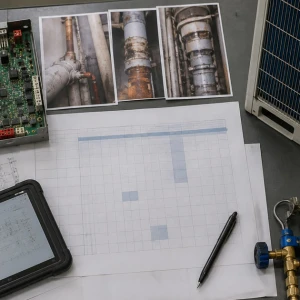
ClimateService documents system map, design basis supplied, instruments, operating state, initial and final readings, valve positions, pump context, module response, limitations, open defects, plant dependencies, photographs, and follow-up within its scope. Facility teams receive settings that can be restored and audited instead of undocumented throttling.