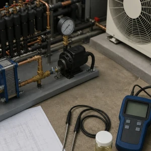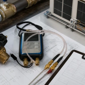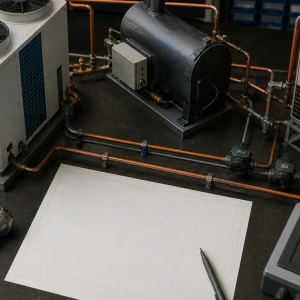


Commercial water-source VRF service joins a multi-zone refrigerant system to a shared condenser-water loop and its pumps, cooling towers, boilers or other heat-addition equipment, treatment, controls, and seasonal operation. A zone or compressor complaint can originate locally, inside the VRF network, or in the plant. ClimateService evaluates authorized Chicago systems while generic hydronic, boiler, tower, treatment, and BAS ownership stays explicit.
Map VRF and water-loop architecture
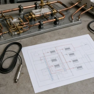
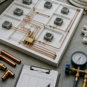
Identify VRF modules, indoor units, branch devices, refrigerant circuits, water connections, valves, strainers, pumps, towers, boilers, heat exchangers, controls, served zones, schedules, criticality, and available drawings. Note which equipment shares the loop. An incomplete map can send repeated repairs to cabinets that are responding correctly to poor water conditions.
Define the complaint with plant context
Record affected zones, modes, time, weather, load, loop supply and return temperatures, pump and tower or boiler state, valve position, alarms, pressure or flow evidence where available, recent treatment or plant work, and whether other water-source units are affected. Simultaneous symptoms often reveal the boundary.
Inspect module water-side components
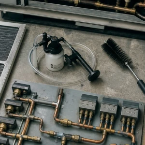
Isolation and control valves, actuators, strainers, hoses, piping, insulation, vents, drains, heat exchangers, leaks, corrosion, supports, temperature sensors, flow proof, and service access influence each module. A commanded valve does not prove flow, and a clean strainer does not prove suitable loop temperature or differential pressure.
Verify flow and temperatures under load
Entering and leaving water temperatures, temperature difference, pressure or flow where authorized, valve authority, pump status, concurrent demand, module stages, heat rejection or addition, and sensor accuracy should be correlated. One reading outside the failure window can miss morning warm-up, afternoon rejection limits, low-load instability, or seasonal transitions.
Evaluate refrigerant operation with water conditions
Compressors, inverter drives, valves, refrigerant temperatures and pressures, piping, oil evidence, safeties, current, and staging depend on usable heat exchange. Low flow, high or low water temperature, fouling, sensor bias, or valve problems can create protection events that resemble refrigerant faults. Both sides belong in diagnosis.
Coordinate pumps and loop distribution
Pump staging, variable drives, differential-pressure control, bypasses, balancing valves, branch pressure, strainers, air, expansion, makeup, and simultaneous building demand affect delivery. VRF-specific observations can define a branch problem, while generic hydronic balancing or pump redesign remains a separate qualified scope.
Review tower and boiler integration
Cooling-tower availability, basin and fan operation, condenser-water temperatures, boiler enable, heat exchanger, heat-addition setpoints, seasonal lockouts, plant sequencing, alarms, and minimum equipment operation may influence the VRF loop. Equipment-specific service should route plant findings without absorbing complete tower or boiler ownership.
Include water treatment and cleanliness
Scale, corrosion, debris, biological material, treatment feed, side-stream filtration, blowdown, makeup, cleaning, flushing, sampling, and recent drain-down can affect heat exchangers and strainers. Treatment providers interpret chemistry and program requirements. Mechanical service documents evidence and coordinates work without making health or compliance claims.
Test controls from command to physical response
Module demand, water-valve output, actuator movement, flow proof, pump command, loop temperature, tower or boiler enable, safeties, alarms, BAS points, overrides, schedules, and restart should be traced. Building-wide programming remains separate, but the water-source VRF sequence needs end-to-end functional proof.
Plan service across shared operations
Water isolation, drain-down, affected modules and zones, plant load, weather, pumps, tower or boiler availability, treatment restoration, access, work hours, temporary conditioning, and communication shape execution. A valve or strainer service can affect more than the visible cabinet. Boundaries and restoration should be written.
Verify local, loop, and zone outcomes
Testing may include module flow evidence, water temperatures, valves, strainers, pumps, refrigerant response, indoor units, branch devices, controls, alarms, tower or boiler coordination, and representative zones. Seasonal or plant-load limitations should receive deferred observations, responsible owners, and response thresholds.
Use focused trends for intermittent plant effects
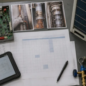
Purposeful trends can compare module demand, valve command, loop temperatures, flow proof, pump speed, differential pressure, tower or boiler status, refrigerant stages, alarms, and affected zones through the complaint window. Sampling interval should match the event. A controller screenshot without physical valve and water evidence rarely proves the true delivery condition.
Keep strainers and service points maintainable
Valve access, strainer blowdown or removal space, insulation closures, drains, gauges or test ports where designed, labels, ceiling or mechanical-room clearance, and spill protection determine whether future service can be completed cleanly. Repeated inaccessible work increases downtime and encourages skipped inspection. Findings should be carried into retrofit or capital scope when access cannot be corrected routinely.
Separate temporary plant support from permanent correction
A forced pump, opened valve, reduced module load, isolated branch, or temporary temperature adjustment may stabilize zones while repair is planned. The measure should identify capacity, energy and freeze implications, monitoring, expiration, approval, and restoration. It should not become undocumented operating logic or substitute for correcting failed plant, hydronic, control, or VRF components.
ClimateService provides a shared-system baseline
ClimateService documents VRF and loop mapping, complaint context, water and refrigerant evidence, corrected module components, plant coordination, settings, photographs, tested modes, unavailable conditions, open hydronic or treatment work, and next maintenance within its scope. Facility teams receive clear responsibility boundaries instead of repeated cabinet-only service.