


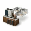
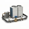

A commercial variable refrigerant flow system is a network rather than a single condensing unit. Outdoor or water-source modules coordinate refrigerant flow with branch devices, indoor units, sensors, controls, communication, and operating modes across many zones. A complaint in one space can be local, but it can also reflect addressing, piping, shared capacity, sequence, heat recovery, or a plant-side dependency.
Confirm the VRF architecture before assigning the fault
Useful system information includes manufacturer and series, outdoor or source modules, heat-pump or heat-recovery configuration, branch controllers or selector boxes, indoor-unit types, piping groups, controls gateways, addressing, served zones, and service history. Water-source and geothermal VRF add condenser-water or ground-loop boundaries that must be included where relevant.
Route the request by the required decision
Repair addresses an active fault or degraded function. Maintenance follows a recurring network-aware scope. Installation creates the equipment, piping, controls, power, drainage, access, and commissioning project. Replacement or upgrade evaluates compatibility, phased work, controls, refrigerant, piping reuse, downtime, and acceptance. Dedicated pages own these intents, while this category explains the complete family.
VRF fault isolation follows the network pattern
Complaints may affect one indoor unit, one piping group, one mode, several zones, or the complete system. Intake should identify affected and normal areas, error history, current mode, timing, outdoor conditions, occupancy, recent controls or tenant changes, and whether the condition follows simultaneous heating and cooling, defrost, staging, or a schedule transition.
Evaluation can include communication, addressing, sensors, commands, indoor fans, coils, electronic expansion devices, branch devices, outdoor modules, compressors, safeties, refrigerant-circuit evidence, piping temperatures, drainage, controls gateways, and connected source-water conditions. Error codes guide the path but do not replace physical confirmation.
Refrigerant piping and branch devices define shared boundaries
Piping layout, branch orientation, insulation, oil return, charge basis, service valves, accessible joints, and branch-controller operation can affect multiple indoor units. Concealed piping limits what can be observed directly. Findings should distinguish confirmed evidence from conditions that require isolation, additional access, pressure testing, monitoring, or a separate project scope.
Controls and addressing are part of system operation
Local controllers, central controllers, schedules, mode priority, group settings, sensors, gateways, and BAS integration can change zone behavior. A displayed command or error does not prove physical response. Service compares the intended sequence, network communication, equipment action, and occupied-space result without treating every control complaint as a failed board.
Maintenance must cover both assets and network history
A planned scope may address indoor-unit filters, coils, fans, drains, pumps where installed, sensors, visible piping and insulation, branch devices, outdoor-module coils and fans, electrical and control connections, operating modes, error history, and applicable manufacturer checks. Access, occupancy, ceiling conditions, season, hours, and system architecture determine task depth.
Water-source VRF adds a condenser-water decision
Entering water conditions, flow, valves, strainers, pumps, loop temperature, controls, boiler, cooling tower, or other heat-rejection equipment can influence water-source modules. The VRF equipment and the plant must be read together when the evidence crosses that boundary. Water treatment and unrelated central-plant work remain separately managed responsibilities.
Geothermal VRF adds ground-loop dependencies
Ground-loop flow, pumps, heat exchangers where present, valves, air removal, controls, and seasonal loop temperatures can affect system behavior. Evaluation must distinguish module operation from loop or pumping conditions. Design or environmental claims require project-specific engineering evidence and should not be inferred from equipment type alone.
Installation requires piping, controls, and commissioning discipline
Selection and design consider loads, diversity, simultaneous modes, ventilation strategy, equipment locations, piping lengths and elevation, branch devices, drainage, power, controls, service access, acoustics, structure, firestopping, insulation, refrigerant requirements, and manufacturer limits. Installation quality must be documented before startup through appropriate cleanliness, pressure, evacuation, charge, addressing, and connection processes.
Replacement and upgrades need compatibility review
Outdoor modules, indoor units, branch controllers, local controls, gateways, refrigerant, and communication generations may not be freely interchangeable. A phased upgrade needs a verified compatibility boundary and operating plan. Reusing piping requires evidence about dimensions, condition, cleanliness, routing, insulation, pressure integrity, and manufacturer acceptance.
Commissioning verifies network behavior
Startup confirms equipment readiness, addressing, communications, piping and charge documentation, drainage, and safe initial operation. Functional testing follows modes, indoor-unit response, branch behavior, central controls, alarms, simultaneous demand where applicable, defrost, source-water response, and representative zones. Seasonal conditions may require later verification.
Prepare a VRF service request
Provide system brand and series if known, module and indoor-unit designations, error history, affected and normal zones, current mode, central-controller information, recent changes, ceiling and mechanical access, operating restrictions, and an authorized contact. Water-source or geothermal systems also need available loop temperatures, pump and plant status, and responsible trade contacts.
Choose the correct VRF resource
Use dedicated pages for repair, maintenance, installation, replacement and upgrades, water-source VRF, geothermal VRF, condenser-water balancing, or boiler and cooling-tower integration. Broader controls/BAS, hydronic, ventilation, capital-planning, and tenant-improvement pages retain separate intent where the decision extends beyond the VRF network.
Request commercial VRF or VRV service
ClimateService provides commercial VRF and VRV service in Chicago and nearby suburbs. Complete network, zone, control, access, and source-side information helps route the request to the correct technical scope without treating the system as a conventional split or rooftop unit.